
Structural Light Steel Framing
Infill
Typical details
Screw Fixed Panel
- Stud
- Track
- Fix to concrete with Tapcon anchors at 600mm centres or nails at 200mm centres
- Refer to fixing guide for edge distances
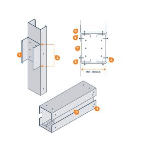
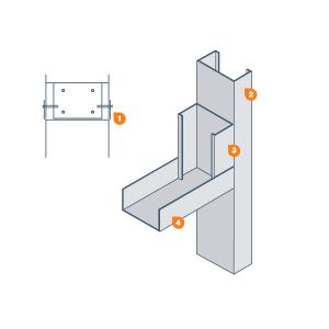
SFS Compound Lintel
- Short section - see design for No. of screws to jamb
- Equal to depth of back to back studs in lintel
- Stud sections to be cut short by flange depth of short section
- Fixings to be added after lintel is in position over short section
- Track
- Track (design may omit)
- 2 No. studs
- Indicates positions screws required at 300mm centres and maximum 150mm from each end
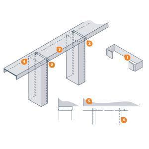
Compound member
- Top of stud to be kept below underside of track web
- Top of wrap-around track to be kept 25mm below bottom of track flang
- Deflection Bracket
- Top Track
- Track
- Track fixed to stud with screws at a maximum of 300mm centres at each flange
Compound member of Stud and Track
- Track section fixed to stud with screws at a maximum of 300 centres at each flange
- Base track
Track section Lintel
- Track
- Full height jamb stud
- Min 150mm section fixed with 4 No screws
- Track forming head to opening 2 No screws at each flange to stud
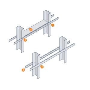
Blocking to Studs
- VB38 lateral bracing on both sides. Note - joints between straps are to be butted together and not lapped
- Solid blocking (of stud section) cut to fit tight between studs. Blocking typically every third bay but may be placed between every stud at teh request of design
- 1 No. screw at each stud and 3 No. per blocking piece each flange
- Bracing channel to be fixed both sides of panels tooling into stud
- At stud positions cut both flanges and flatten out. 2 No. screws to each stud
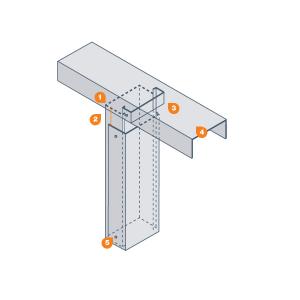
SFS Deflection Head type 3
- Deflection bracket
- Deflection bracket at every stud and fixed to track with 1 No. screws to each flan
- Deep runner track
- Stud must not be screwed to track. Top of stud 15 to 25mm below underside of track
- Top track fixed to concrete/hot rolled frame at 600 centres
- 15 - 25mm deflection gap between top of stud and underside of track
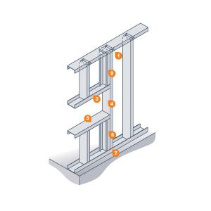
Double jamb with type 3 Deflection Head
- Deflection bracket attached to jamb stud qand cripple stud
- Cripple stud extends to head track. Fix to jamb stud with 2 No. screws at 300mm vertical centres
- Opening Lintel
- Jamb stud. Example here is single jamb however compound jambs can be used
- Opening Cill
- Jamb stud. Example here is single jamb however compound jambs can be used
- Cripple stud extends to base track. Fix to jamb stud with 2 No. screws at 300mm vertical centres
- Jamb stud and cripple stud both fixed to base track
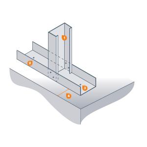
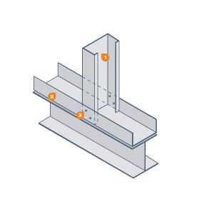
Stud Connection to Track 03
- Stud
- Tracks
- Typically 1 No screw for each flange for infill walling. Typically 2 No screws for each flange for SFS loadbearing walls
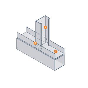
Stud Connection to Track
- Stud
- Track
- Typically 1 No screw for each flange for infill walling. Typically 2 No screws for each flange for SFS loadbearing walls
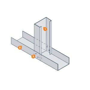
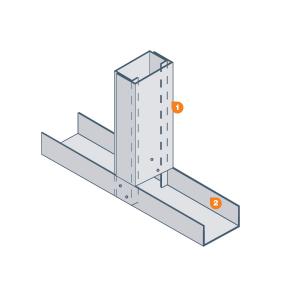
Stud Connection to Track 02
- Stud
- Track
- Typically 1 No screw for each flange for infill walling. Typically 2 No screws for each flange for SFS loadbearing walls